


-
 E-mail: yidek@126.com
 -
 Tel: 400-8262-889
 -
 Fax: 0577-85600699
 -
 Contact: Mr. Ji
Contact Us
State Grid Chengbu Power Supply Branch Typical experience of three-phase unbalance adjustment
1 Introduction
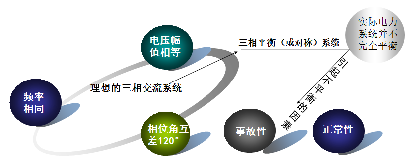
The three-phase voltage source of a three-phase balanced circuit must be a sine wave with the same frequency, the same amplitude, and 120 degrees difference in phase; the three-phase load impedance is the same and both are linear impedances, so the three-phase currents are all sine waves. And the frequency is the same, the amplitude is the same, and the phases are 120 degrees out of each other.
Absolute three-phase balance does not exist, and the actual three-phase system always has different degrees of imbalance. The grid hopes that the three-phase current of the user load will be balanced as much as possible. Otherwise, the three-phase unbalanced current will cause the transformer capacity to be wasted and the neutral current to be too large. The grid hopes that the reactive current of the user load is as small as possible, otherwise the reactive power is in the grid. Circulating back and forth with the load, resulting in wasted power; the grid hopes that the harmonic current of the user load is as small as possible, otherwise the harmonics will cause the grid voltage and current to be distorted, causing the equipment to work abnormally; the user wants the voltage amplitude provided by the grid to be more stable. Well, otherwise too high or too low voltage will cause equipment protection or even damage.
2, the concept of three-phase imbalance
Accidental imbalance: due to the failure of one phase (or two phases) in a three-phase system, such as one-phase or two-phase disconnection, or single-phase ground fault. This condition is not allowed by the operation of the system. It is necessary to remove the fault in a short period of time to restore the system to normal.
Normality imbalance: due to system three-phase components or load asymmetry. The "three-phase voltage allowable imbalance" as one of the power quality indicators is determined for normal unbalanced operating conditions.
3. National standards and regulations for three-phase unbalance
National standard
Allowable value of voltage imbalance
GB/T 15543-1995 stipulates that the normal voltage unbalance degree of the common connection point of the power system is 2%, and the short-term time shall not exceed 4%. This is based on a comprehensive analysis of important electrical equipment (rotary electrical machine) standards, grid voltage imbalance analysis, foreign similar standards and electromagnetic compatibility standards.
GB755-1981 "Basic Technical Requirements for Electric Machines" stipulates that the maximum value of I2/IN for continuous operation of synchronous motor is 0.08-0.10, while the negative sequence impedance of rotating motor is about 0.14-0.45, if the unbalance of machine end is 2%, The corresponding current imbalance is 0.044-0.14, which may exceed the long-term capacity of the negative sequence current of the motor. However, as the common connection point, there is only a very small number of direct distribution power supply networks. There is generally the impedance of the line and transformer between the actual rotating electrical machine and the common connection point. As long as the reduced impedance of these components can reach 0.1 or more, the corresponding negative sequence current is expected to fall below 8% of the rated current. Of course, the negative sequence withstand capability of the rotating electrical machine is also related to the bearing condition of the motor itself. If the motor is not fully loaded, it can naturally afford more negative sequence current.
National regulations
For the distribution transformer area where the outlet current imbalance is more than 15% and the load ratio is greater than 60%, which is difficult to adjust by management measures, a three-phase unbalance automatic adjustment device is required.
For the "low voltage" problem caused by various factors such as low voltage harmonics, voltage flicker, and insufficient reactive power compensation capacity, a low voltage reactive power generator (SVG) is required.
It is stipulated that the normal voltage imbalance degree of the common connection point of the power system is 2%, and the short-term imbalance is not allowed to exceed 4%. The permissible value for each user accessing the common connection point causing the normal pressure imbalance at that point is typically 1.3%.
Second, the danger of three-phase imbalance
1, increase the power loss of the line
In a three-phase four-wire power supply network, when a current passes through a line conductor, power loss is generated due to the presence of a yin resistance, and the loss is proportional to the square of the passing current. When the low-voltage power grid is powered by a three-phase four-wire system, it is inevitable that the three-phase load is unbalanced due to the presence of a single-phase load. When the three-phase load is unbalanced, there is current flowing through the neutral line. In this way, not only the phase line is depleted, but also the neutral line is also depleted, which increases the loss of the grid line.
2. Increase the power loss of the distribution transformer
The distribution transformer is the main power supply equipment of the low-voltage power grid. When it is operated under the unbalanced three-phase load condition, it will cause an increase in the distribution loss. Because the power loss of the distribution varies with the imbalance of the load.
In the production and living power, when the three-phase load is unbalanced, the transformer is in an asymmetrical operation state. Increased transformer losses (including no-load losses and load losses). According to the transformer operating regulations, the neutral current of the transformer in operation shall not exceed 25% of the rated current of the low-voltage side of the transformer. In addition, the unbalanced operation of the three-phase load will cause the zero-sequence current of the transformer to be too large, and the temperature rise of the local metal parts may even cause the transformer to burn out.
3, the distribution of output reduction
When the transformer is designed, the winding structure is designed according to the load balance operation condition, and the winding performance is basically the same, and the rated capacity of each phase is equal. The maximum allowable output of the distribution is limited by the rated capacity of each phase. If the distribution transformer is operated under the unbalanced load condition of the three-phase load, the light-loaded one phase will have a surplus capacity, thereby reducing the output of the distribution transformer.
The degree of reduction in output is related to the imbalance of the three-phase load. The greater the three-phase load imbalance, the more the distribution output is reduced. For this reason, the distribution transformer operates when the three-phase load is unbalanced, and the output capacity cannot reach the rated value, the standby capacity is also reduced correspondingly, and the overload capability is also reduced. If the distribution is operated under overload conditions, it will easily cause the distribution to heat up, and even in severe cases, it will cause the distribution to burn.
4, the distribution produces zero sequence current
When the distribution transformer is operated under the unbalanced three-phase load condition, a zero-sequence current will be generated, which will vary with the degree of unbalance of the three-phase load. The greater the imbalance, the larger the zero-sequence current. If there is a zero-sequence current in the running distribution, a zero-sequence flux will be generated in the core. (There is no zero-sequence current on the high-voltage side) This forces the zero-sequence flux to pass through the tank wall and the steel member as the passage, while the magnetic permeability of the steel member is low, and the hysteresis and eddy current are generated when the zero-sequence current passes through the steel member. Loss, so that the local temperature of the steel member with the distribution changes and heats up. The winding insulation of the transformer is accelerated due to overheating, which leads to a decrease in the life of the device. At the same time, the presence of the zero sequence current also increases the loss of the distribution.
5. Affect the safe operation of electrical equipment
When the three-phase load is unbalanced, the output current of each phase is not equal, and the internal three-phase voltage drop of the distribution is not equal, which will inevitably lead to three-phase unbalance of the distribution output voltage. At the same time, the distribution transformer operates when the three-phase load is unbalanced. The three-phase output current is different, and the neutral line will have current. As a result, the neutral line produces a negative pressure drop, which causes the neutral point to drift, causing the phase voltages to change. The voltage of one phase of the load is reduced, while the voltage of one phase of the load is increased. When the voltage is unbalanced, the user equipment that is easy to cause a high voltage is burnt out, and the user of the voltage that is connected to one of the users may not be used. Therefore, when the three-phase load is unbalanced, the safe operation of the electrical equipment will be seriously jeopardized.
The occurrence of three-phase voltage imbalance will lead to the occurrence of several times of current imbalance, which induces an increase in the reverse torque of the motor, which causes the temperature of the motor to rise, the efficiency to decrease, the energy consumption to increase, the vibration to occur, and the output loss to be affected. The imbalance between the phases can lead to shortened service life of the electrical equipment, accelerate the frequency of equipment component replacement, and increase the cost of equipment maintenance. The circuit breaker allows the current margin to decrease, and overload and short circuit are likely to occur when the load changes or alternates. An excessively large unbalanced current flows into the neutral line, causing the neutral line to thicken.
Third, the cause of three-phase imbalance
1. Reasons for three-phase unbalance of distribution transformer
The power of the power grid is three-phase, but the general civilian load is single-phase. There are also two-phase loads such as electric welding. The welding equipment is connected between the two phases. The transient current is used to generate a large current to melt the metal because the load is Two-phase, resulting in no current in one phase of the three-phase current on the grid side, so there will be an imbalance.
Generally, in the power distribution, the single-phase load is intentionally distributed on the three-phase, for example, the three-story building, the first floor is connected to the A phase, the second floor is connected to the B phase, and the third floor is connected to the C phase, so that a general Three-phase balance. The above premise is that residents are still built in the case of stable living, while individual rural areas have problems with the mobility of residents during the Spring Festival and after the Spring Festival. At this time, the labor has evenly distributed the balance of the use of each phase, because the residents return home at the end of the year and the Spring Festival to rework two nodes will cause three-phase imbalance.
Unbalance can result in wasted transformer capacity, increased N-line current, neutral offset, etc., and therefore requires governance.
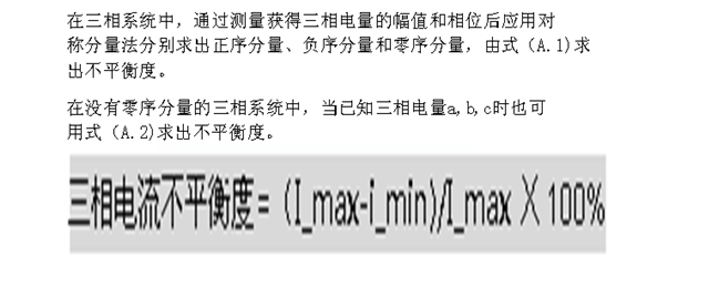
2, parameter calculation
We know that the calculation formula for the three-phase load unbalance rate of distribution transformers is:
Three-phase load unbalance rate = (maximum phase negative load - minimum phase load) / maximum phase load * 100%
(The national standard for distribution of three-phase load unbalance rate is not more than 15%, and the neutral current is not more than 25% of the rated current of the transformer).
The unbalanced expression is:
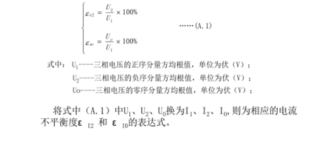
The exact calculation of the imbalance is:
3, adjust the feasibility analysis
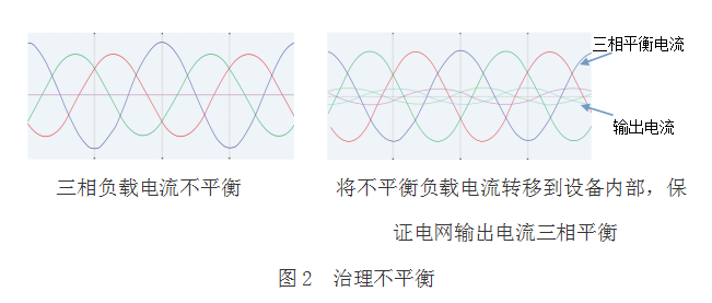
The principle of governing three-phase imbalance
After the three-phase unbalanced treatment device is turned on, the system current is detected in real time by an external current transformer (CT), and the system current information is sent to the internal controller for processing and analysis to determine whether the system is in an unbalanced state, and at the same time, the balance is calculated. In the state, the current value of each phase needs to be converted, and then the signal is sent to the internal IGBT and its action is driven, the unbalanced current is transferred from the phase with large current to the phase with small current, and finally reaches the three-phase equilibrium state. As shown below:

2, to avoid equipment false alarm caused by local voltage imbalance
3, to avoid the risk of zero voltage of the ground caused by the weak system of the control system burned down
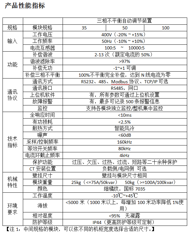
Unbalanced specifications
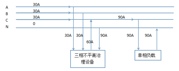
1. For the three-phase grid current, the output ABC is 30A, and the N-line current is 0, reaching the three-phase complete balance.
2. For single-phase load, phase C current input is 90A, and N line output is 90A.
3. For unbalanced treatment equipment, phase A and phase B flow into 30A, phase C output is 60A, and line N flows into 90A.
This ensures that the three-phase unbalanced treatment equipment maintains a complete balance of the three-phase grid current even in the case of a single-phase load.
The original unbalanced current flows into the grid through the N line, and now the unbalanced current on the load side still exists, but all of it flows into the three-phase unbalanced treatment equipment.
Governance
Reduce the user's own electricity expenses, the power factor reaches the national standard, avoid the power rate penalty caused by the low power factor, reduce the line loss, reduce the voltage drop and increase the actual use capacity of the transformer and generator.
Summary--ability analysis to solve the three-phase imbalance
1. Reasonably distribute the asymmetric load in the three phases to make the load of each phase as balanced as possible;
2. Disperse the asymmetric load at different power supply points, and reduce the imbalance caused by the centralized connection;
3. Connect the asymmetric load to the higher voltage supply. The higher the voltage level, the larger the system short-circuit capacity, the smaller the proportion of the asymmetric load in the total system load, and the lower the voltage three-phase unbalance. For single-phase load, if the short-circuit capacity of the system is more than 50 times of the load capacity, the voltage three-phase unbalance of the connection point can be less than 2%;
4. The asymmetric load is supplied by a separate transformer;
5. Power supply is provided by a balanced transformer with special wiring. The balance transformer is a special transformer for three-phase-two-phase functions with both buck and commutation. Using it to power can improve power quality and reduce power loss. It is currently used to power electrified railways and large induction furnaces.
6, install three-phase current balance device
to sum up:
In the above six ways of discussion, the first five programs are impossible to be comprehensive regardless of capital investment, manual management difficulty and feasibility analysis.
The sixth solution, the addition of a three-phase current balancing device, is the most effective, most ideal and most comprehensive solution through the above analysis.
Fourth, the first 1# public change three-phase unbalance adjustment
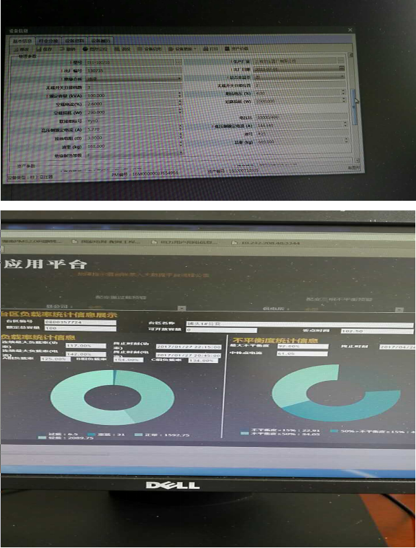
1, basic parameters
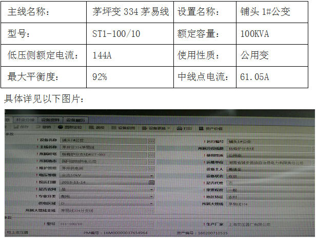
Specific parameters of the head 1# public change
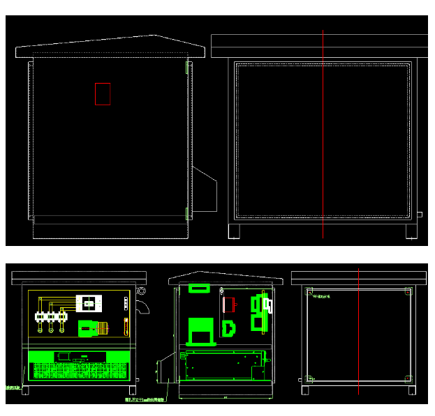
Product Structure
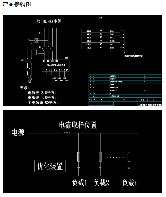
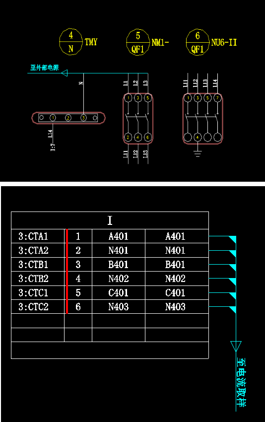
Product secondary wiring diagram
2, the adjustment device design capacity design
According to the basic information of the 1# public change of the shop head, the variable voltage rated capacity is 100KVA, and the corresponding low-voltage side rated current is 144A. According to this information, the design and configuration products are three-phase.
The unbalanced adjustment device has a capacity of 100kvar, and the device 100kvar is I=100/U/1.732=144A, which can fully meet the adjustment and optimization use of this shophead 1# public change, and has a margin for use.
Optimize power quality.
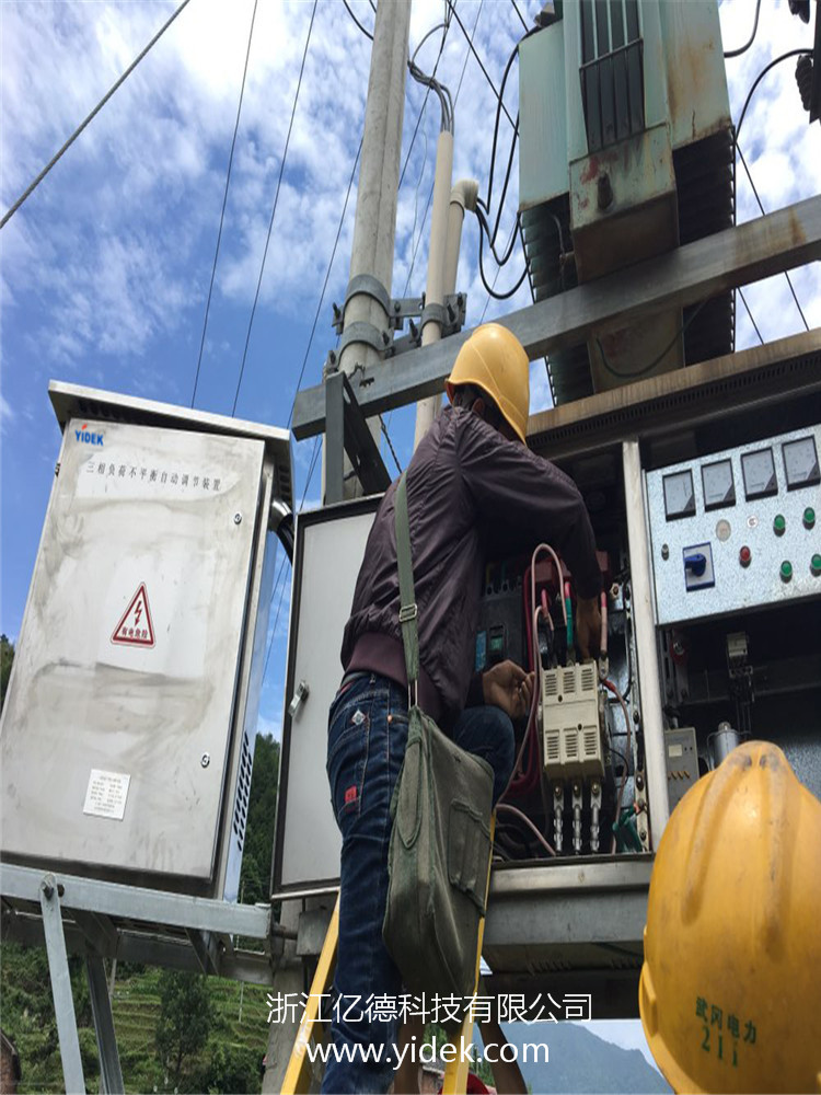
4, the installation process
Initial inspection
Before installing the adjustment device, first check the following:
1. Visually inspect the exterior and interior of the adjustment unit for transport damage. In case of damage, please inform the carrier immediately.
2. Check the product label to confirm the correctness of the equipment. The device casing is affixed with a nameplate and a brow indicating the type, capacity and main parameters of the adjustment device.
Selection
Adjustment device installation position
The adjustment device should be installed in a clean environment and should be well ventilated to ensure that the ambient temperature meets product specifications.
The regulating device is provided with forced air cooling by an internal fan, and the cold air enters the inside of the adjusting device through the wind grill in front of the adjusting device cabinet, and the hot air is discharged through the wind grill at the rear of the adjusting device.
Do not block the ventilation holes.
The adjustment device can be selected from rack mounting, flat mounting and wall mounting. In order to facilitate the maintenance of the adjustment device during daily operation, in addition to meeting local regulations,
The inlet end of the adjustment device should have enough space to facilitate the access of the maintenance personnel.
|
note! |
u If the installation mode is wall-mounted, at least 150mm of inlet and outlet air space should be reserved at the upper and lower exits of the module. u If the installation mode is cabinet mode, at least 600mm of inlet and outlet air space and rear maintenance space should be reserved at the front and rear outlets of the cabinet. u If necessary, install an indoor exhaust fan to avoid room temperature increase |
In order to extend the service life, the choice of the position of the adjustment device should ensure:
1. Easy wiring
2. There is enough room for operation
3. Good ventilation to meet the heat dissipation requirements
4. There is no corrosive gas around
5. No excessive humidity and high temperature source
6. Non-dusty environment
7. Meet fire protection requirements
There are power terminals and CT input terminals at the incoming end of the adjustment unit chassis. The front panel of the adjustment device has a main touch screen for centralized operation and display operation status.
Handling of the device
|
note! |
u Since the weight of a single regulating device module is 30kg-50kg, it is recommended to carry it by two people in a short distance. If it is to be transported over a long distance, it needs to be completed by certain transportation equipment. |
The three-phase four-wire adjustment device to the mid-line cable of the load depends on the compensation harmonics. Because the third and third multiple harmonics flow through the neutral line, the specification of the neutral cable is about twice that of the incoming cable (otherwise the neutral line may be hot. Lead to danger).
The incoming cables for the regulators at each current level are as follows:
Table 4.7 Cable Specifications
|
Device rated current |
50A |
100A |
150A |
200A |
250A |
300A |
350A |
|
Copper cable (mm2) |
16 |
35 |
50 |
95 |
120 |
150 |
185 |
|
Aluminum cable (mm2) |
|
|
|
|
|
|
After completing the wiring of the first line and the wiring of the external sampling CT according to the user manual, after confirming that the completion is correct, the next step of power-on debugging and the completion of the entire installation process.


Governance effect
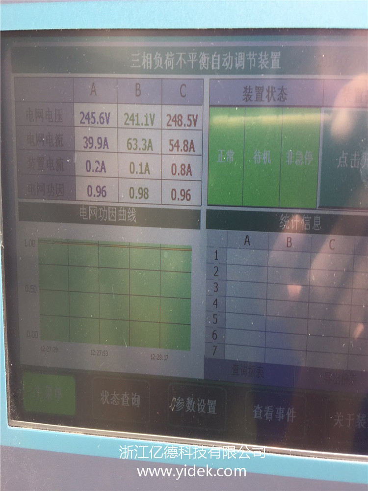
Not running control
Note: Three-phase load unbalance rate = (maximum phase negative load - minimum phase load) / maximum phase load * 100%
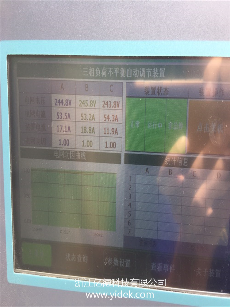
After booting and running the governance
Note: Three-phase load unbalance rate = (maximum phase negative load - minimum phase load) / maximum phase load * 100%
Installation location: Shop 1# bus
The transformers in this area are publicly variable, and the transformer is 100KVA. The users mainly build houses for local residents. The main purpose is to catering and self-occupation. The load is mainly single-phase lighting, air conditioning, heating
The equipment is mainly. The three-phase load imbalance phenomenon is serious, and there is a big hidden danger to the long-term stable operation of the transformer.
1. Three-phase load imbalance may cause serious consequences of burning the transformer:
If the heavy-duty phase current is too large during unbalance, the overload will be excessive, which may cause overheating of the winding and transformer oil. The winding is overheated and the insulation aging is accelerated; the transformer oil is overheated, causing oil quality deterioration.
Rapidly reduce the insulation performance of the transformer, reduce the life of the transformer (for every 8 °C increase in temperature, the service life will be reduced by half), and even burn the winding.
2. The unbalanced operation of the three-phase load will cause the zero-sequence current of the transformer to be too large, and the temperature rise of the local metal parts will increase:
In a three-phase load unbalanced operation, the transformer will inevitably produce zero-sequence current, and the existence of zero-sequence current inside the transformer will generate zero-sequence flux in the core. These zero-sequence fluxes will
It will form a loop in the tank wall of the transformer or other metal components. However, when the distribution transformer is designed without considering these metal members as magnetic conductive members, the resulting hysteresis and eddy current loss are caused.
The heating of these components causes the temperature of the local metal parts of the transformer to rise abnormally, which may cause a transformer operation accident.
actual data
|
|
Phase A current (A) |
Phase B current (A) |
Phase C current (A) |
Phase A power factor |
Phase B power factor |
Phase C power factor |
|
Before installation |
40.2 |
70.5 |
54.9 |
0.96 |
0.98 |
0.96 |
|
After installation |
53.5 |
53.2 |
54.3 |
1.00 |
1.00 |
1.00 |
(70.5-40.2) / 70.5 = 43%
The three-phase load imbalance after installation is:
(54.3-53.2)/54.3=2%
After the device is put into operation, there is a significant improvement in the three-phase unbalance for the case where the load is not large, and the effect is more obvious as the load is increased. And the reactive power compensation power factor is improved, the transformer loss is reduced, the operation is stable, the power consumption is low, and the effect is obvious.