 E-mail:
  Tel: 400-8262-889
 Fax: 0577-85600699
 Contact: Mr. Ji
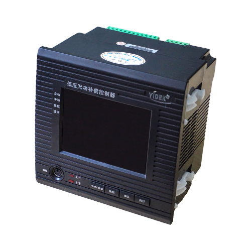
 Skype Online
 yidek@126.com
 Product Manual
 400-8262-889
 Problem
 Product Case
 Product Certificate
 Relevant information
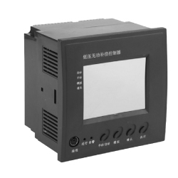
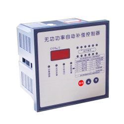
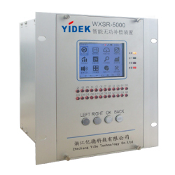
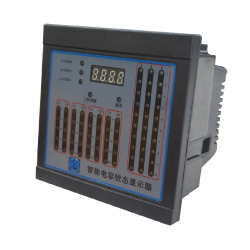
The reactive power compensation controller (referred to as the controller) is a new generation low-voltage reactive power compensation controller designed and developed according to the relevant national technical standards, procedures and user's actual requirements, using a dedicated power parameter acquisition chip and a 32-bit ARM processor. The product is beautiful in appearance and easy to install and use. Man-machine dialogue is achieved through the digital game and the buttons. Connected to the YD series of intelligent integrated power capacitors via 485 communication. The control physical quantities are a combination of voltage, current, power factor and reactive power. The new reactive power trend estimation algorithm is especially suitable for occasions with large power factor variations. The number of actions is small and the control accuracy is high.
Product parameters
Features
1. Data such as voltage, current, power, and power factor are obtained through AC sampling, and the reactive power shortage is calculated. The harmonic distortion rate of the total voltage and current can be calculated by collecting the voltage and current of each phase from 2 to 10 harmonics.
2. Dynamic display of the various parameter values of the power distribution, the parameter setting is simple and fast, and the set parameters are not lost.
3. Automatically detect the number and capacity of smart capacitors, and lose power according to the grid reactive parameters.
4. With overvoltage, undervoltage, undercurrent, overtemperature, voltage and current harmonic protection, when the grid parameters exceed the set limits, the controller quickly cuts off the capacitor that has been put in, and blocks the output, protecting the capacitor safely and prolonging Its service life.
5. Using voltage, current, power factor, reactive power and other comprehensive calculations, the voltage hysteresis participates in the control judgment, making the compensation more precise and preventing the switching oscillation.
6. Multi-sampling the above-mentioned criterion value during the action delay time, and performing reactive power trend judgment according to the value of each point, avoiding the judgment error caused by the single-point sampling of the action point of the conventional controller, and the power factor fluctuation is large. In this case, the reactive power and compensation direction (cast or cut) of the required compensation can be accurately determined.
7. With manual / automatic switching function. When set to automatic, the capacitor is input or cut according to the combination of voltage, load, power factor and reactive power shortage. When the manual is set, the input or cut of the capacitor can be manually operated, which is convenient for factory debugging and fast switching capacitor. Analog switching can be achieved in both manual and automatic states.
8. The principle of switching: Capacitors of the same capacity are switched according to the number of actions, the first action with the least number of actions, and the capacitors of different capacities are operated according to the reactive power shortage.
Use environment
Ambient temperature: -25~70°C
Altitude: ≤2000m
No flammable medium exists, no conductive dust and corrosive gas are present.
measurement accuracy
Voltage: ≤±0.5% (in the range of 80%~120% rated voltage)
Current: ≤±1.0% (in the range of 80%~120% rated voltage)
Power factor: ≤ ± 1.5%
Reactive power: ≤±2.0%
Temperature: ≤1°C
output method
Communication control output, control of our smart capacitors
Power supply condition
Working voltage: 220V AC
Voltage deviation: ±20%
Rated frequency: 50Hz ± 5%
Power consumption: <5W
Number of networking stations: distribution ≤ 12 units Total number ≤ 24 units
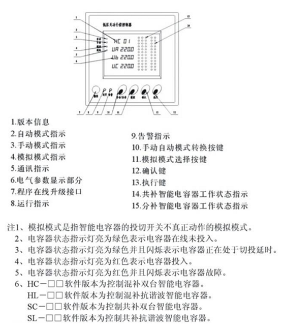
Product model and display panel
Product installation and electrical wiring
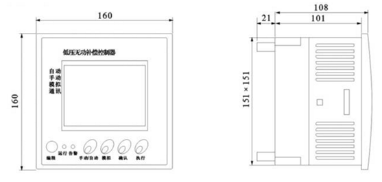
Mechanical installation: Open a square hole of 151X151mm on the screen cabinet, push the controller into the square hole from the front of the screen, insert the fasteners into the installation slot, and tighten the screws to fix the controller on the screen.
Electrical Wiring: Electrical wiring is defined by the electrical wiring schematic diagram on the controller housing and the output terminals.
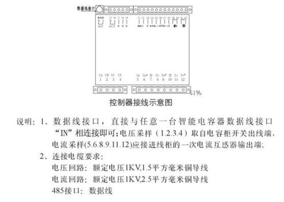
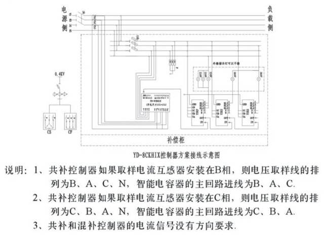
Product wiring diagram
If you have any enquiry about quotation or cooperation,please feel free to email us at yidek@126.com or use the following enquiry form. Our sales representative will contact you within 24 hours. Thank you for your interest in our products.
- Subject:
- *Name:
- *Email:
- Company Name:
- Tel:
- Fax:
- Country:
- Message: